The general structure of the transistor is three outputs, one control and two commuting. In a bipolar transistor, the control pin is called the base, in a field-effect transistor, the gate. The commuting pins in a bipolar transistor are called an emitter (emission - emit) and a collector (collect - collect). In a field-effect transistor, the switching terminals are called the source (charge source) and drain (charge collection).
Bipolar transistor
A bipolar transistor has three outputs - one control, a base, and two switching ones - an emitter and a collector. The current in the transistor has two streams: one of them is the base-emitter current, the second is the emitter-collector. Since there is no base-collector current movement , the names base current and collector current are used for brevity.When the voltage on the base increases relative to the emitter, electrons are formed on the base, which create a bridge that allows electrons to go between the emitter and the collector. Accordingly, the more electrons there are on the base, the more current passes between the switched terminals.
Bipolar transistors come in two types, NPN and PNP. In a transistor, N stands for negative, P stands for positive. NPN forms a "bridge" at a positive base-emitter voltage, PNP at negative, the current, respectively, in these transistors flows in different directions.The main characteristic of a bipolar transistor is the current gain, hfe, showing the ratio of the collector current increase with the base current increase. At the same time, the base-emitter voltage has its limitations.
Restrictions
Consider the BC547C transistor. Any imported transistor is accompanied by a technical specification (datasheet): specification for transistor BC547.
Cut-off voltage
The voltage on the base must lie in a certain range, so that the transistor is open, this range is called the cut-off voltage (Base-Emitter On Voltage) and for the BC547 transistor lies in the range of 0.58-0.7 V, this is the spread parameters, that is, buying a transistor, you can expect that the cut-off voltage will lie in this range, although more often it will be closer to the nominal value of 0.66 V.
Collector current
The maximum current that can pass through the collector is specified in the documentation, for BC547 it is a current equal to 0.1A = 100 mA. The collector current graph, depending on the voltage on the base, ends where the maximum allowable current lies, as soon as the voltage reached the maximum value - the transistor is fully open, it switched to saturation mode, the maximum value is also indicated in the plate on the first page, VBE (base-emitter saturation voltage). When switching to saturation mode, the transistor ceases to control the current, then it lets everything pass through it and if you pass more than the maximum allowable current through it, then it will simply start to heat up until it will burn out, and this process sometimes takes a fraction of a second.
Application of a bipolar transistor
Current gain
To calculate, we need to determine the current that will flow through the load element. Let's take an LED with the following parameters: voltage 1.6 V, current 10 mA.
The transistor controls the collector current by means of the base current and our task is to determine the base current to maintain a current of 10 mA through the collector. Let's turn to the technical documentation, on graph No. 3 the dependence of hfe on the collector current is depicted, we see that in the 0-10 mA section the value of hfe is constant, therefore we consider the calculated value to be a constant and take the average for this transistor (at the end of the first the page describes the classification depending on the letter in the name of the transistor, for C the value of hfe will be lie in the range of 420-800, which means that you may come across a transistor with both a value of 420 and 800. Let's take the average - 600 for calculation)
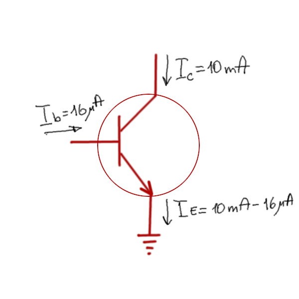
Collector current depending on the base current: Ib = Ic/hfe = 10 / 600 = 0.016 mA = 16 ma
The static characteristic graph (No. 1 in the documentation) shows a combination of three values: base current, collector current, collector-emitter voltage drop. With a base current of 16 Ma and a collector current of 10 mA, the voltage on the collector it will be close to the emitter voltage, in the case of the circuit below - zero:
Any device requires power, as a rule, standard ones are used, for 3.3 V digital equipment, for small devices 3V (two AA batteries), 5V (USB), 9V (crown battery). Let's take 3.3 volts as an example.
Based on schedule No. 2 (in the documentation), with a collector current of 10 mA, the voltage on the base should be about 0.72 V, we will create the required voltage and current by applying a resistor. The supply voltage is 3.3 V, from where the resistance of the base resistor will be as follows:
R = U/I = (3.3-0.72) V / 0.016 mA = 161 250 Ω

We could order the manufacture of a resistor of this nominal value, but there is always a tolerance in which we work, this is and the influence of temperature and the resistance of the tracks on the board and noise and many other factors, so we take the nearest available denomination in the catalog (if you work for a company, you always have a supplier, which provides a product catalog, if you make a device for yourself - you look at what is in the store). The nearest available nominal value is 160 kOhm.
The voltage on the LED should be equal to 1.6 V, a resistor will be required to create a voltage drop:
R = U/I = (3.3-1.6) V / 10 mA = 170 Ω
We look in the catalog, 160 or 180 are available to us, we will choose 180, so it will be safer for the LED.
Bipolar transistor sound amplifier
To amplify the sound, the same principle is used as for amplifying the current, the principle of operation is as follows: an amplified signal is supplied to the base, the signal voltage must not be lower than the cut-off voltage.